

How To Use A Sperry Voltmeter
Introduction
-
-
A continuity exam tells usa whether two things are electrically connected: if something is continuous , an electric current can menses freely from one end to the other.
-
If there's no continuity, it ways there is a suspension somewhere in the circuit. This could indicate anything from a blown fuse or bad solder joint to an incorrectly wired circuit.
-
-
-
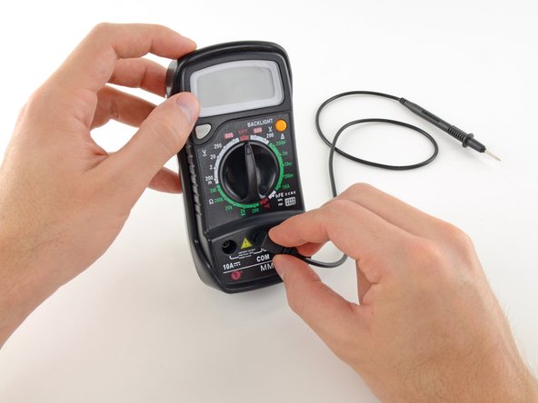
Plug the black probe into the COM port on your multimeter.
-
Plug the red probe into the VΩmA port.
-
-
-
Switch on your multimeter, and gear up the punch to continuity mode (indicated by an icon that looks like a sound wave).
-
-
-
The multimeter tests continuity by sending a niggling current through one probe, and checking whether the other probe receives it.
-
If the probes are connected—either by a continuous circuit, or by touching each other directly—the test electric current flows through. The screen displays a value of zip (or near zero), and the multimeter beeps. Continuity!
-
If the test electric current isn't detected, information technology means there's no continuity. The screen will display i or OL (open loop).
-
-
-
To complete your continuity test, place one probe at each stop of the circuit or component you want to test.
-
As before, if your circuit is continuous, the screen displays a value of nothing (or virtually zippo), and the multimeter beeps.
-
If the screen displays 1 or OL (open loop), there'due south no continuity—that is, there'due south no path for electric current to flow from i probe to the other.
-
-
-
If your multimeter doesn't have a dedicated continuity test mode, you tin can still perform a continuity test.
-
Turn the dial to the lowest setting in the resistance way.
-
-
-
In this fashion, the multimeter sends a little electric current through i probe, and measures what (if annihilation) is received by the other probe.
-
If the probes are connected—either past a continuous circuit, or by touching each other straight—the exam electric current flows through. The screen displays a value of zero (or near zero—in this case, 0.viii). Very low resistance is another way of saying that nosotros have continuity.
-
If no current is detected, information technology means there's no continuity. The screen will brandish one or OL (open up loop).
-
-
-
To complete your continuity test, identify one probe at each stop of the circuit or component you want to test.
-
As before, if your circuit is continuous, the screen displays a value of zero (or near zero).
-
If the screen displays 1 or OL (open loop), there's no continuity—that is, there'south no path for electric electric current to flow from one probe to the other.
-
-
-
Plug the black probe into the COM port on your multimeter.
-
Plug the blood-red probe into the VΩmA port.
-
-
-
Switch on your multimeter, and ready the dial to DC voltage style (indicated by a 5 with a directly line, or the symbol ⎓).
-
Most multimeters are not autoranging, meaning you will need to ready the correct range for the voltage y'all expect to mensurate.
-
Each setting on the dial lists the maximum voltage it can mensurate. So for case, if y'all look to measure out more than than two volts but less than xx, use the twenty volt setting.
-
If you're not sure, start with the highest setting.
-
-
-
Place the cerise probe on the positive terminal, and the blackness probe on the negative concluding.
-
If your range was gear up too high, you may not get a very accurate reading. Here the multimeter reads ix volts. That's fine, but we tin plow the dial to a lower range to become a better reading.
-
If yous gear up the range too low, the multimeter only reads 1 or OL, indicating that information technology is overloaded or out of range. This won't hurt the multimeter, but we demand to set the punch to a higher range.
-
-
-
With the range set correctly, we become a reading of nine.42 volts.
-
Reversing the probes won't do any harm; it just gives u.s.a. a negative reading.
-
-
-
To begin, make certain no electric current is running through the circuit or component you want to examination. Switch it off, unplug it from the wall, and remove any batteries.
-
Plug the black probe into the COM port on your multimeter.
-
Plug the red probe into the VΩmA port.
-
-
-
Switch on your multimeter, and set up the dial to resistance mode.
-
Nearly multimeters are not autoranging, meaning yous will demand to set the correct range for the resistance you await to measure. If y'all're not sure, showtime with the highest setting.
-
-
-
Place one probe at each end of the circuit or component you want to test.
-
If your multimeter reads shut to nix, the range is set too high for a practiced measurement. Turn the dial to a lower setting.
-
If you ready the range too depression, the multimeter simply reads ane or OL, indicating that it is overloaded or out of range. This won't injure the multimeter, simply nosotros need to set the punch to a higher range.
-
The other possibility is that the circuit or component you are testing doesn't have continuity—that is, information technology has infinite resistance. A non continuous circuit will ever read one or OL on a resistance test.
-
-
-
With the multimeter set up to a usable range, we become a reading of 1.04k ohms.
-


Embed this guide
Choose a size and copy the code below to embed this guide every bit a small widget on your site / forum.
Preview

How To Use A Sperry Voltmeter,
Source: https://www.ifixit.com/Guide/How+To+Use+A+Multimeter/25632
Posted by: fitzgeraldlecous.blogspot.com
0 Response to "How To Use A Sperry Voltmeter"
Post a Comment